Zone Sensor Module (ZSM) Testing
Mechanical Zone Sensor Module
Temperature Input
Terminals to Read Voltage: RTRM J6-1, J6-2
Read DC voltage with the sensor attached. If voltage does not appear to be correct, read the resistance of the circuit, then the sensor itself, to see if a problem exists in the sensor or the wiring. With the sensor not
attached there should be 5.00 VDC at the terminals as shown below.
Problems to Look for:
• Mis-wire/short/open
• Excessive resistance in circuit (corroded or loose connection)
• Sensor inaccurate (should be ± 2F of chart)
• Moisture in sensor (becomes accurate when dry)
• Induced voltage (high voltage wires in same conduit)
Service Tips
To check for induced voltage, read AC voltage to ground from each sensor wire. Should be less than 1 VAC.
Figure 66. Temperature input / voltmeter display
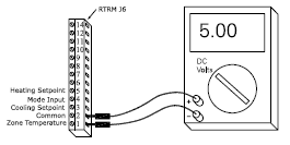
Table 1. Temperature input
| Temp °F | Resistance (Kohms) | DC Volts |
| 40 | 26.097 | 3.613 |
| 41 | 25.383 | 3.585 |
| 42 | 24.69 | 3.557 |
| 43 | 24.018 | 3.528 |
| 44 | 23.367 | 3.5 |
| 45 | 22.736 | 3.471 |
| 46 | 22.123 | 3.442 |
| 47 | 21.53 | 3.412 |
| 48 | 20.953 | 3.383 |
| 49 | 20.396 | 3.353 |
| 50 | 19.854 | 3.324 |
| 51 | 19.33 | 3.294 |
| 52 | 18.821 | 3.264 |
| 53 | 18.327 | 3.233 |
| 54 | 17.847 | 3.203 |
| 55 | 17.382 | 3.173 |
| 56 | 16.93 | 3.142 |
| 57 | 16.491 | 3.111 |
| 58 | 16.066 | 3.08 |
| 59 | 15.654 | 3.05 |
| 60 | 15.253 | 3.019 |
| 61 | 14.864 | 2.988 |
| 62 | 14.486 | 2.957 |
| 63 | 14.119 | 2.926 |
| 64 | 13.762 | 2.895 |
| 65 | 13.416 | 2.864 |
| 66 | 13.078 | 2.832 |
| 67 | 12.752 | 2.801 |
| 68 | 12.435 | 2.77 |
| 69 | 12.126 | 2.739 |
| 70 | 11.827 | 2.708 |
| 71 | 11.535 | 2.677 |
| 72 | 11.252 | 2.646 |
| 73 | 10.977 | 2.616 |
| 74 | 10.709 | 2.58 |
| 75 | 10.448 | 2.554 |
| 76 | 10.194 | 2.523 |
| 77 | 9.949 | 2.493 |
| 78 | 9.71 | 2.462 |
| 79 | 9.477 | 2.432 |
| 80 | 9.25 | 2.402 |
| 81 | 9.03 | 2.372 |
| 82 | 8.815 | 2.342 |
| 83 | 8.607 | 2.312 |
| 84 | 8.404 | 2.283 |
| 85 | 8.206 | 2.253 |
| 86 | 8.014 | 2.224 |
| 87 | 7.827 | 2.195 |
| 88 | 7.645 | 2.166 |
| 89 | 7.468 | 2.137 |
| 90 | 7.295 | 2.109 |
| 91 | 7.127 | 2.08 |
| 92 | 6.963 | 2.052 |
| 93 | 6.803 | 2.024 |
| 94 | 6.648 | 1.996 |
| 95 | 6.497 | 1.969 |
Setpoint Input
Terminals to Read Voltage: RTRM J6-3 (cooling), J6-5 (heating), J6-2
Read DC voltage with Zone Sensor Module (ZSM) attached. If voltage read does not appear to be correct,
read the resistance of the circuit, then the ZSM itself, to see if a problem exists in the ZSM or the wiring. With the ZSM not attached there should be 5.00 VDC at the terminals as shown. To check for induced voltage, read AC voltage to ground from each sensor wire. Should be less than 2VAC.
Table 2. Setpoint input / voltmeter display
| Setpoint Inputs | Read voltage at RTRM or | Read voltage at ZSM |
| Cooling setpoint | RTRM J6-3 | ZSM terminal 3 |
| Heating setpoint | RTRM J6-5 | ZSM terminal 5 |
| Common | RTRM J6-2 | ZSM terminal 2 |
Problems to Look for:
• Mis-wire/short/open
• Excessive resistance in circuit (corroded or loose connection)
• Setpoint lever inaccurate (should be +-2F of chart)
• Induced voltage (high voltage wires in same conduit)
Table 3. Setpoint inputs
| Temp °F | Resistance (Kohms) | DC Volts |
| open | 5.00(open circuit) | |
| 40 | 1.0841 | 2.601 |
| 41 | 1.0656 | 2.579 |
| 42 | 1.0472 | 2.557 |
| 43 | 1.287 | 2.535 |
| 44 | 1.0102 | 2.513 |
| 45 | 0.9918 | 2.49 |
| 46 | 0.9733 | 2.466 |
| 47 | 0.9548 | 2.442 |
| 48 | 0.9363 | 2.418 |
| 49 | 0.9179 | 2.393 |
| 50 | 0.8994 | 2.368 |
| 51 | 0.8787 | 2.338 |
| 52 | 0.858 | 2.309 |
| 53 | 0.8373 | 2.278 |
| 54 | 0.8166 | 2.247 |
| 55 | 0.7958 | 2.216 |
| 56 | 0.7751 | 2.183 |
| 57 | 0.7544 | 2.15 |
| 58 | 0.7337 | 2.116 |
| 59 | 0.7142 | 2.083 |
| 60 | 0.6948 | 2.05 |
| 61 | 0.6753 | 2.015 |
| 62 | 0.6558 | 1.98 |
| 63 | 0.6363 | 1.944 |
| 64 | 0.6169 | 1.908 |
| 65 | 0.5974 | 1.87 |
| 66 | 0.5779 | 1.831 |
| 67 | 0.5584 | 1.792 |
| 68 | 0.539 | 1.751 |
| 69 | 0.5195 | 1.709 |
| 70 | 0.5 | 1.667 |
| 71 | 0.4805 | 1.623 |
| 72 | 0.461 | 1.578 |
| 73 | 0.4416 | 1.532 |
| 74 | 0.4221 | 1.484 |
| 75 | 0.4026 | 1.435 |
| 76 | 0.3832 | 1.385 |
| 77 | 0.3637 | 1.333 |
| 78 | 0.3442 | 1.28 |
| 79 | 0.3247 | 1.226 |
| 80 | 0.3053 | 1.169 |
| 81 | 0.2858 | 1.111 |
| 82 | 0.2663 | 1.051 |
| 83 | 0.2468 | 0.99 |
| 84 | 0.2273 | 0.926 |
| 85 | 0.2079 | 0.86 |
| 86 | 0.1884 | 0.793 |
| 87 | 0.1689 | 0.723 |
| 88 | 0.1495 | 0.65 |
| 89 | 0.1301 | 0.575 |
| 90 | 0.1106 | 0.498 |
| (Shorted/No Power) | 0 | 0 |
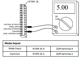
Mode Input
Terminals to Read Voltage: RTRM J6-4, J6-2
Read DC voltage with Zone Sensor Module (ZSM) attached. If voltage read does not appear to be correct,
read the resistance of the circuit, then the ZSM itself, to see if a problem exists in the ZSM or the wiring. With the ZSM not attached there should be 5.00 VDC at the terminals listed above. To check for induced voltage, read AC voltage to ground from each sensor wire. Should be less than 2VAC.
Figure 68. Mode input / Voltage reading
Problems to Look for:
• Mis-wire/short/open
• Excessive resistance in circuit (corroded or loose connection)
• Induced voltage (high voltage wires in same conduit)
Table 4. Zone sensor readings
| System Switch | Fan Switch | Ohms Rx1K | Volts DC +/= 5% |
| Short to common | 0 | 0 | |
| OFF | AUTO | 2.32 | 0.94 |
| COOL | AUTO | 4.87 | 1.64 |
| AUTO | AUTO | 7.68 | 2.17 |
| OFF | ON | 10.77 | 2.59 |
| COOL | ON | 13.32 | 2.85 |
| AUTO | ON | 16.13 | 3.08 |
| HEAT | AUTO | 19.48 | 3.3 |
| HEAT | ON | 27.93 | 3.68 |
| EM HEAT | AUTO | 35 | 3.88 |
| EM HEAT | ON | 43.45 | 4.06 |
| Open circuit | 5 |
WARNING:
Information in this article is intended for use by individuals possessing adequate backgrounds of electrical and mechanical experience and who comply with all federal, state, and local laws, rules, orders, or regulations related to the installation, service, or repair of a heating or central air conditioning product. Any attempt to install, service, or repair a heating or central air conditioning product may result in personal injury and/or property damage. The manufacturer or seller cannot be responsible for the interpretation of the information contained herein, nor can it assume any liability in connection with its use.